Symbols serve as a universal language facilitating effective communication. Among the diverse symbols, valve symbols take prominence as a vital category.
Valves, integral to regulating fluid flow in piping systems, make grasping valve symbols a crucial skill for engineers and technicians alike, ensuring seamless understanding and communication in the field.
What Are Valve Symbols and How Are They Used?
Valve symbols are graphical representations used in industrial engineering to convey information about different types of valves and their functions within piping systems.
These symbols provide a visual shorthand for engineers, technicians, and other professionals, enabling them to quickly understand the type of valve, its operation, and its role in controlling fluid flow.
Valve symbols are part of a standardized system that enhances communication, design, and documentation in various engineering disciplines, ensuring a common understanding across different teams and projects.
What is a Piping & Instrumentation Diagram (P&ID)?
UN Piping and Instrumentation Diagram (P&ID) is a comprehensive illustration employed in engineering to depict the intricate network of piping and related components within a physical process flow.
It intricately outlines the interconnections among process equipment and the instrumentation pivotal for process control.
Serving as a foundational tool for the maintenance and modification of represented processes, P&IDs play a vital role in conveying the entire engineering process concerning the development and installation of a process plant.
This detailed diagram effectively communicates relationships between equipment, piping, control flow, and various control devices.
How Important is the P&ID?
Essential for comprehending the design conditions of an engineering project, P&IDs facilitate efficient operation, maintenance, and modification of process systems.
With a keen focus on control, shutdown safety, regulatory requirements, and basic operational details, they lay out and demonstrate the physical sequence of systems conveniently.
P&IDs encompass crucial elements, including mechanical equipment, valve identifications, process piping details, miscellaneous items, flow directions, control inputs and outputs, and various other annotations to ensure clarity and precision.
However, P&IDs have their limitations. They are not drawn to scale or geometrically accurate, lacking a universally accepted standard.
Variations may exist between companies and even within the same company based on internal standards, software systems, and creator preferences.
Typically crafted by engineers, P&IDs find application across various project stages, from design and construction to operations, safety management, environmental compliance, and quality management, serving as a fundamental tool throughout the lifecycle of a project.
Valve Types Per Category and Their Symbols
Credits to: Gemini Valve
Category #1: Two-Way Valves
A 2-way, on/off valve, is visually represented by two equilateral triangles converging towards each other.
This symbol is part of a standardized system where different lines are employed to signify various valve types.
To enhance clarity, an arrowhead at the line’s end indicates the direction of flow. This symbol is integral to interpreting valve functions in engineering and industrial contexts.
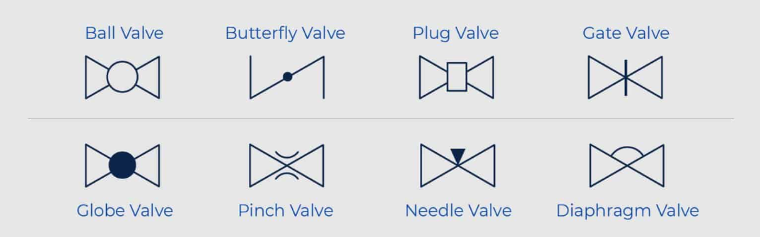
Common Types of 2-Way Valves and Their Symbols
Credits to: Gemini Valve
Ball Valve Symbol
- Symbolized by a hollow circle intersected by a perpendicular line.
- Valvole a sfera utilize a rotating ball to control flow.
Butterfly Valve Symbol
- Represented by a circle with a centrally placed short line.
- Valvole a farfalla employ a disc mounted on a shaft for fluid regulation.
Plug Valve Symbol
- Depicted by a hollow shape intersected by a short perpendicular line.
- Plug valves feature a cylindrical or tapered plug to manage fluid flow.
Gate Valve Symbol
- The symbol includes two perpendicular lines parallel to the flow direction.
- Saracinesche use a wedge-shaped gate to control fluid passage.
Globe Valve Symbol
- Symbolized by a circular body with an arrow extending from it.
- Valvole a globo involve a movable plug or disc for flow control.
Pinch Valve Symbol
- Represented by an oval shape with a perpendicular line crossing it.
- Controls flow using a flexible tube that can be pinched shut.
Needle Valve Symbol
- Depicted by a long, tapered needle intersecting a line.
- Features a pointed needle for precise flow adjustment.
Diaphragm Valve Symbol
- The symbol includes two perpendicular lines with a curved line passing through it.
- Utilizes a flexible diaphragm to regulate fluid flow, isolating the valve from the process stream.
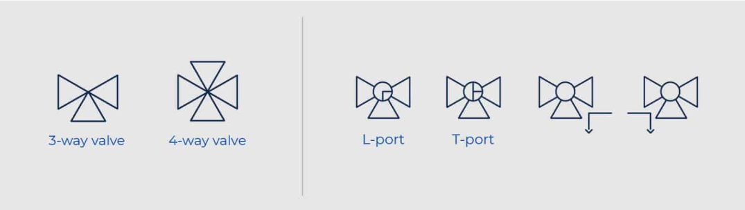
Category #2: Three-Way & Four-Way Valves
Multi-port valves, such as 3-way and 4-way valves, introduce additional elements to their symbols for clarity:
Credits to: Gemini Valve
L-Port and T-Port Valves
- In L-port valves, an additional line within the ball symbol represents the flow path resembling an “L.”
- T-port valves showcase a line forming a “T” within the ball symbol, indicating the flow paths.
Symbol Modification
- Additional triangles are incorporated into the valve symbol to signify multiple ports or paths.
- These triangles provide a visual indication of the valve’s complexity and functionality.
Flow Path Representation
- Small arrows accompanying the symbol illustrate the flow direction through each port.
- This feature enhances the clarity of how fluid moves within the valve.
Understanding these modifications is crucial for engineers and technicians, ensuring accurate interpretation and effective communication in process diagrams and schematics.
Other Valve Types and Their Symbols
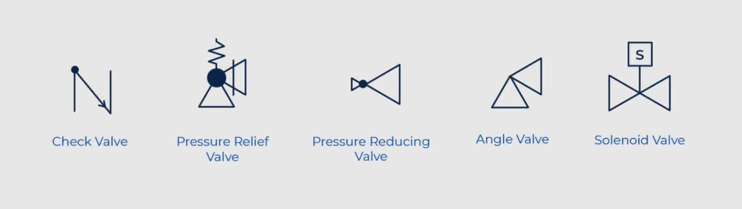
Credits to: Gemini Valve
Simbolo della valvola di ritegno
- Typically represented by a right-angled arrow, the check valve symbol indicates a one-way flow path.
- Function: Controlla le valvole help prevent backflow by allowing fluid or gas to flow in one direction only, ensuring system integrity.
Pressure Relief Valve Symbol
- Displayed as a valve with a spring and an arrow, symbolizing the pressure relief mechanism.
- Function: Safeguards systems by releasing excess pressure, preventing damage, and ensuring safety during pressure fluctuations.
Pressure Reducing Valve Symbol
- Depicted as a valve with an arrow pointing downward and an adjustment knob.
- Function: Regulates and reduces high inlet pressures to a lower, manageable level, maintaining optimal operational conditions.
Angle Valve Symbol
- Shown as a valve with a 90-degree bend in the flow path.
- Function: Installed at angles in pipelines, angle valves are versatile components controlling the flow with a right-angled design.
Solenoid Valve Symbol
- Represented by a box with a control loop and an arrow indicating the solenoid’s actuation.
- Function: Controlled by an electromagnetic solenoid, these valves are used for automated and precise fluid control in various applications.
Chiave da asporto
Understanding these symbols is vital for professionals in the field, facilitating effective communication and accurate representation of valve types in engineering drawings and diagrams.
It streamlines collaboration among engineers, ensuring everyone interprets system designs consistently.
Proficient interpretation of valve symbols enhances project efficiency, reducing errors and promoting the seamless integration of valves into complex industrial processes.