
Industrial piping systems demand precision and reliability, especially when it comes to valve connections. A single dimensional mismatch can lead to costly delays, safety hazards, and system failures. Understanding gate valve flange dimensions ensures seamless integration, proper sealing, and long-term operational success across diverse applications from oil and gas facilities to municipal water systems.
Gate valve flange dimensions represent the standardized measurements that govern how these critical flow control devices connect to piping networks. Whether you’re specifying a new installation or planning a replacement project, mastering these dimensional requirements is essential for system integrity and operational efficiency.
This comprehensive guide covers everything you need to know about gate valve flange dimensions, from ANSI B16.5 standards to material considerations and practical selection criteria. You’ll discover how proper dimensional specifications ensure compatibility, prevent installation issues, and support reliable long-term performance.
Understanding Gate Valve Flange Dimensions
Gate valve flange dimensions refer to the standardized measurements for flanged end connections on gate valves. These precision-engineered surfaces create the critical interface between the valve body and piping system, ensuring proper alignment, sealing, and structural integrity under operating conditions.
The ANSI B16.5 standard governs flange dimensions for pressure classes 150# through 2500#, establishing uniform specifications that manufacturers worldwide follow. This standardization means a gate valve manufactured in one location will properly mate with piping components from another manufacturer, provided both follow the same dimensional standards.
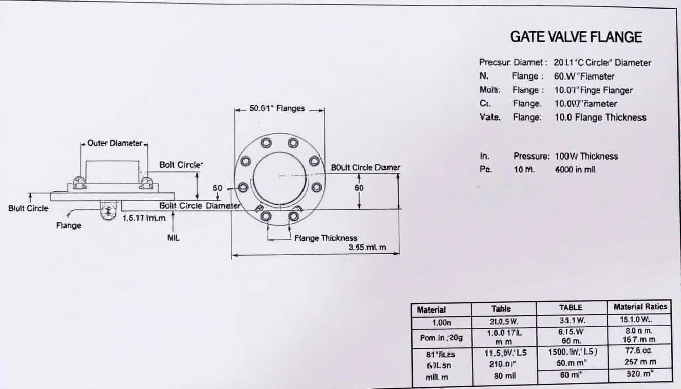
Key dimensional parameters include bolt circle diameter, bolt hole size, flange thickness, and outside diameter. Each of these measurements serves a specific engineering purpose:
Bolt Circle Diameter: Determines the spacing and number of fasteners required for proper joint integrity
Outside Diameter: Establishes clearance requirements and structural load distribution
Flange Thickness: Provides adequate material for pressure containment and bolt load distribution
Bolt Hole Diameter: Ensures proper fastener fit and joint preload capability
Proper flange dimensions ensure compatibility between valves and piping systems while maintaining the pressure rating integrity throughout the installation. These standardized dimensions also facilitate easy operation during maintenance activities, as replacement components can be specified with confidence in their dimensional compatibility.
The importance of standardized dimensions extends beyond simple compatibility. In high-pressure applications, dimensional accuracy affects gasket compression, bolt stress distribution, and overall joint reliability. Even minor deviations from standard dimensions can compromise system safety and performance.
ANSI B16.5 Flange Dimension Standards
ANSI B16.5 specifies raised face flange dimensions for gate valves from 1/2” to 24” nominal sizes, covering the vast majority of industrial valve applications. This standard represents decades of engineering experience and field testing, providing reliable dimensional specifications that support safe, leak-free operation.
The standard covers pressure classes 150#, 300#, 600#, 900#, 1500#, and 2500#, with each class designed for specific pressure and temperature conditions. Higher pressure classes feature larger bolt patterns and increased flange thickness to handle greater mechanical and pressure loads.
Ring type joint (RTJ) dimensions for high-pressure applications are also specified within ANSI B16.5. These specialized flange faces use metal ring gaskets and require precise groove dimensions to achieve reliable sealing in extreme service conditions.
Flat face flange specifications accommodate specific applications where raised face designs are not suitable, particularly in cast iron piping systems or where uniform gasket compression across the entire flange face is required.
| Nominal Size | Class 150# OD | Class 300# OD | Class 600# OD | Bolt Circle | Number of Bolts |
| 2” | 6.00” | 6.50” | 7.50” | 4.75” | 4 |
| 4” | 9.00” | 10.00” | 11.00” | 7.50” | 8 |
| 6” | 11.00” | 12.50” | 14.00” | 9.50” | 8 |
| 8” | 13.50” | 15.00” | 16.50” | 11.75” | 8 |
| 12” | 19.00” | 20.50” | 22.00” | 17.00” | 12 |
Pressure Class Dimensional Requirements
Class 150# flanges represent the standard for pressures up to 285 PSIG at ambient temperature, making them suitable for many municipal and light industrial applications. These flanges feature the smallest bolt patterns and thinnest profiles for their respective sizes, optimizing material usage while meeting pressure requirements.
Class 300# through 2500# designs address higher pressure applications with correspondingly larger bolt patterns and increased material thickness. The progression follows engineering principles where higher pressures require greater bolt preload and more robust flange geometry to maintain joint integrity.
Bolt circle diameter increases with pressure class for the same nominal size, accommodating larger and more numerous fasteners. For example, a 4-inch valve transitions from 8 bolts in Class 150# to 8 larger bolts in Class 300#, then to 8 even larger bolts in Class 600# and above.
Flange thickness varies based on pressure rating and material specifications, with each class engineered to handle specific stress levels. The thickness progression ensures adequate material for bolt load distribution while maintaining the structural integrity required for safe operation.
Understanding these dimensional progressions helps engineers select appropriate pressure classes without over-specifying equipment. Using a Class 300# flange in a Class 150# system introduces unnecessary cost and weight, while under-specifying pressure class can lead to catastrophic failure.
Gate Valve Size Range and Dimensional Specifications
Small bore valves ranging from 1/2” to 2” feature compact flange dimensions designed for instrumentation and process control applications. These valves often incorporate precision-machined surfaces and specialized sealing arrangements to ensure reliable performance in critical control loops.
Medium bore valves from 3” to 12” are commonly used in industrial and municipal applications where flow rates and pressure drops must be carefully balanced. These sizes represent the sweet spot for many piping systems, offering good flow capacity while maintaining manageable installation requirements.
Large bore valves from 14” to 48” handle high-flow applications with substantial flange dimensions that require careful consideration of support structures and installation procedures. These installations often need specialized lifting equipment and custom supports to handle the significant weight and dimensions involved.
Stainless steel gate valves are available in sizes 1/2” to 12” per ANSI B16.5 specifications, with larger sizes typically requiring special construction methods. The corrosion resistance and smooth interior surfaces of stainless steel make these valves ideal for food processing, pharmaceutical, and chemical applications.
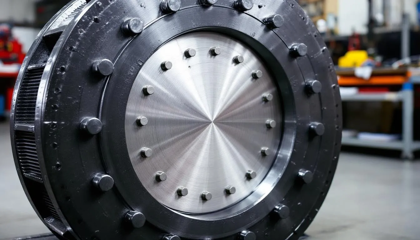
Critical Dimensional Parameters
Outside diameter (OD) represents the overall flange diameter used for clearance calculations and support structure design. This dimension determines the minimum spacing required between adjacent valves and affects the overall piping layout in congested areas.
Bolt circle diameter establishes the center-to-center distance of bolt holes, which directly impacts the installation procedure and bolt access requirements. Proper bolt circle dimensions ensure that fasteners can be installed and torqued correctly without interference from adjacent components.
Bolt hole diameter determines the size of holes for proper fastener selection and installation ease. Standard hole sizes are designed to accommodate specific bolt diameters with appropriate clearance for thermal expansion and installation tolerances.
Flange thickness provides the structural foundation for pressure containment and load distribution. This critical dimension must provide adequate material for bolt threads while maintaining the required strength under operating conditions.
These parameters work together to create a complete dimensional specification that ensures proper fit, function, and safety. Engineers must consider all dimensions simultaneously when specifying gate valves to avoid compatibility issues during installation.
Material Impact on Flange Dimensions
Cast steel gate valves maintain standard ANSI dimensions across pressure classes 150-2500, ensuring broad compatibility with existing piping systems. The robust properties of cast steel allow for thin wall sections while meeting strength requirements, optimizing weight and material usage.
Ductile iron construction follows AWWA C515 specifications for municipal applications, where corrosion resistance and cost-effectiveness are primary concerns. These valves often feature fusion bonded epoxy coatings for enhanced durability in buried service conditions.
Stainless steel flanges conform to ASTM standards while maintaining ANSI B16.5 dimensions, ensuring compatibility across material boundaries. The corrosion resistance and smooth surfaces of stainless steel construction make these valves ideal for sanitary and chemical processing applications.
Carbon steel body construction per ASTM A216 Grade WCB specifications provides excellent strength characteristics while maintaining standard dimensional tolerances. These valves represent the industry standard for general industrial service where moderate temperatures and pressures are encountered.
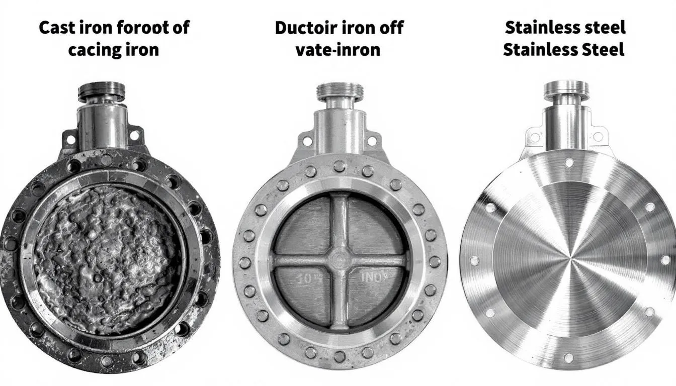
Different materials can affect dimensional tolerances due to varying thermal expansion coefficients and manufacturing processes. Stainless steel typically requires tighter machining tolerances to achieve the same sealing performance as cast iron, while ductile iron offers improved dimensional stability compared to gray cast iron.
The choice of body material also influences gasket selection and bolt torque requirements. Softer materials like cast iron may require lower bolt torques to prevent flange distortion, while harder materials can accept higher preloads for improved sealing performance.
Manufacturing processes vary between materials, affecting the precision and consistency of flange dimensions. Investment casting typically produces more accurate dimensions than sand casting, while machined surfaces provide superior sealing characteristics regardless of base material.
Installation and Gasket Considerations
Raised face flanges require spiral wound or composition gaskets designed to seal against the protruding face surface. The raised face design concentrates gasket compression over a smaller area, improving sealing performance while reducing required bolt torque.
RTJ flanges use metal ring gaskets with specific groove dimensions machined into the flange face. These high-performance sealing systems are designed for extreme pressure and temperature conditions where conventional gaskets cannot provide reliable service.
Bolt hole alignment proves critical for proper installation and sealing performance. Misaligned holes can prevent proper bolt insertion or create uneven gasket compression that leads to leakage and premature gasket failure.
Face-to-face dimensions per ASME B16.10 standards affect piping layout and installation procedures. These standardized lengths ensure that replacement valves fit existing piping without modification, reducing maintenance time and costs.
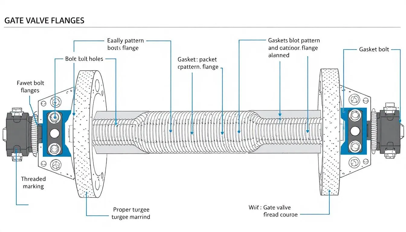
Bolt Pattern and Fastener Requirements
The number of bolts increases with valve size and pressure class to distribute loads evenly across the flange face. Smaller valves may use 4 bolts, while larger sizes require 12, 16, or even 20 bolts to maintain proper sealing under operating conditions.
Bolt sizes range from 1/2” to 1-1/2” depending on flange class and application requirements. The progression follows engineering principles where larger bolts provide greater preload capability and improved fatigue resistance under cyclical loading.
Proper bolt torque specifications ensure reliable joint integrity throughout the service life. Under-torquing can lead to gasket blow-out and leakage, while over-torquing may damage flange surfaces or cause bolt failure during thermal cycling.
Stud bolt lengths are calculated based on flange thickness and gasket type to ensure adequate thread engagement while providing proper compression. The calculations must account for gasket compression, thermal expansion, and bolt stretch under operating loads.
Installation procedures should follow a star pattern for bolt tightening to ensure uniform gasket compression. This approach prevents gasket distortion and ensures consistent sealing performance around the entire flange circumference.
Selection Guide for Gate Valve Flange Dimensions
Matching valve flange class to system pressure rating represents the first and most critical selection criterion. A Class 150# flange rated for 285 PSIG at ambient temperature provides adequate safety margin for most municipal and light industrial applications.
Verification of compatibility with existing piping flange dimensions prevents costly field modifications and installation delays. This step requires careful review of bolt patterns, outside diameters, and flange thickness to ensure proper fit with existing components.
Temperature effects on dimensional tolerances must be considered for elevated temperature service. Thermal expansion can affect bolt preload and gasket compression, requiring careful analysis of temperature cycling effects on joint integrity.
API 600 and ASME B16.34 compliance becomes essential for critical applications where safety and reliability are paramount. These standards provide additional requirements for materials, testing, and quality assurance beyond basic dimensional compliance.
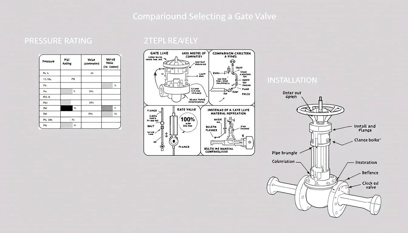
The selection process begins with establishing system operating conditions including pressure, temperature, and fluid characteristics. These parameters determine the minimum pressure class and material requirements for safe operation.
Next, evaluate space constraints and installation requirements that may affect flange selection. Large flanges require adequate clearance for bolt installation and maintenance access, while weight considerations may require additional supports.
Consider future maintenance requirements when selecting flange dimensions. Standardized dimensions facilitate parts availability and reduce inventory requirements, while specialized dimensions may require custom gaskets or fasteners.
Finally, verify that selected dimensions meet all applicable codes and standards for the specific application. Different industries may have unique requirements that exceed basic ANSI B16.5 specifications, requiring careful review of applicable regulations.
The goal is selecting gate valve flange dimensions that provide reliable service while optimizing cost and installation requirements. Proper specification prevents field issues and ensures long-term system performance that meets or exceeds design expectations.
Understanding gate valve flange dimensions represents a fundamental skill for anyone involved in piping system design, installation, or maintenance. The standardized dimensions established by ANSI B16.5 and related standards provide the foundation for reliable, interchangeable connections that have served industry for decades.
Whether you’re designing a new facility or maintaining existing equipment, proper attention to these dimensional requirements ensures system integrity and operational success. The investment in understanding these standards pays dividends through reduced installation time, improved reliability, and enhanced safety performance.
For specific applications or unusual service conditions, always consult the latest editions of applicable standards and consider seeking expert guidance to ensure optimal valve selection and installation practices.


