
Symbols serve as a universal language facilitating effective communication. Among the diverse symbols, valve symbols take prominence as a vital category.
Valves, integral to regulating fluid flow in piping systems, make grasping valve symbols a crucial skill for engineers and technicians alike, ensuring seamless understanding and communication in the field.

What Are Valve Symbols and How Are They Used?
Valve symbols are graphical representations used in industrial engineering to convey information about different types of valves and their functions within piping systems.
These symbols provide a visual shorthand for engineers, technicians, and other professionals, enabling them to quickly understand the type of valve, its operation, and its role in controlling fluid flow.
Valve symbols are part of a standardized system that enhances communication, design, and documentation in various engineering disciplines, ensuring a common understanding across different teams and projects.

What is a Piping & Instrumentation Diagram (P&ID)?
A Piping and Instrumentation Diagram (P&ID) is a comprehensive illustration employed in engineering to depict the intricate network of piping and related components within a physical process flow.
It intricately outlines the interconnections among process equipment and the instrumentation pivotal for process control.
Serving as a foundational tool for the maintenance and modification of represented processes, P&IDs play a vital role in conveying the entire engineering process concerning the development and installation of a process plant.
This detailed diagram effectively communicates relationships between equipment, piping, control flow, and various control devices.

Customize the perfect valve for your project! Get a quote and explore our custom options.
How Important is the P&ID?
Essential for comprehending the design conditions of an engineering project, P&IDs facilitate efficient operation, maintenance, and modification of process systems.
With a keen focus on control, shutdown safety, regulatory requirements, and basic operational details, they lay out and demonstrate the physical sequence of systems conveniently.
P&IDs encompass crucial elements, including mechanical equipment, valve identifications, process piping details, miscellaneous items, flow directions, control inputs and outputs, and various other annotations to ensure clarity and precision.
However, P&IDs have their limitations. They are not drawn to scale or geometrically accurate, lacking a universally accepted standard.
Variations may exist between companies and even within the same company based on internal standards, software systems, and creator preferences.
Typically crafted by engineers, P&IDs find application across various project stages, from design and construction to operations, safety management, environmental compliance, and quality management, serving as a fundamental tool throughout the lifecycle of a project.
🔩 FORGED GLOBE VALVE
Engineered for pressure control in compact and high-pressure pipelines.
Explore Product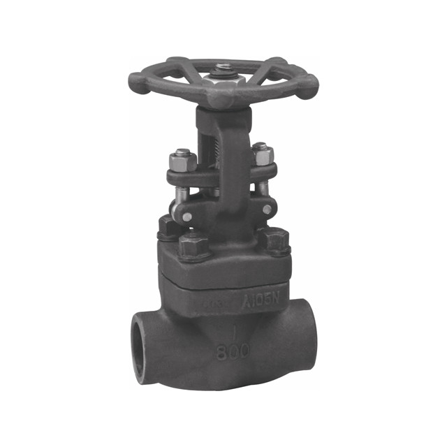
Standardization of Symbols
Valve symbols, along with pipework and flow control valve symbols, are standardized across industries to ensure consistent communication in technical drawings, such as Piping and Instrumentation Diagrams (P&IDs).
These symbols adhere to international standards, such as ISO 14617 and ANSI/ISA-5.1, which specify the graphical representation of valves and other components.
It is crucial for valve manufacturers to follow these standards as they provide clarity and uniformity in the interpretation of complex systems.
Understanding valve symbols, including the ball valve symbol, gate valve symbol, globe valve symbol, and butterfly valve symbol, helps engineers accurately read and interpret P&IDs.
These valve symbols ensure proper system design and troubleshooting.
Types of Valves and Their Symbols
Industrial piping systems utilize various types of valves, each designed for specific functions within the system.
Below are some of the most common valve types, their functions, and their corresponding P&ID symbols.
These symbols, including those for flow control valves, ball valves, and more, help engineers understand the purpose of each valve in controlling the system’s flow, pressure, or direction.
Note: Credits to Assured Automation for all the Valve Symbol images in this article.

2-Way Valves
A 2-way valve has two ports—one for the inlet and one for the outlet—making it the most basic A 2-way valve is the simplest type, with two ports: one for the inlet and one for the outlet.
This design allows for straightforward control over the flow of a fluid.
These valves can operate in either an on/off capacity or through throttling to regulate the flow rate.
The actuation method, whether manual, pneumatic, or electric, determines the valve’s specific function in the system.
All the valves listed below are 2-way valves used across industries for flow control.

| Valve Type | Functions | Valve Symbol |
| Ball Valve | Provides on/off control, commonly used in high-pressure systems due to its robust design. Recognized by the ball valve symbol in P&ID diagrams, this valve offers reliable flow isolation. |  |
| Butterfly Valve | Used for flow regulation, it allows quick operation with minimal pressure drop. The butterfly valve symbol in pipework symbols shows its ability to control large volumes of flow efficiently. |  |
| Plug Valve | Similar to ball valves but with a more compact design, plug valves are used for on/off control. They are ideal for tight spaces and are represented by distinct valve symbols in P&ID drawings. |  |
| Gate Valve | Primarily used for flow isolation, the gate valve symbol in P&ID systems represents its function of either fully opening or fully closing the flow path. |  |
| Globe Valve | Designed for precise flow regulation, the globe valve symbol is widely recognized in P&ID diagrams and pipework symbols, indicating its use in throttling applications. |  |
| Pinch Valve | Ideal for handling slurries or viscous fluids, pinch valves control flow by pinching the flexible tube through which the fluid flows. The valve symbols for pinch valves reflect their unique mechanism in industrial piping systems. |  |
| Needle Valve | Provides fine adjustment of flow rate, especially in systems requiring precise control. The needle valve symbol is used in P&ID symbols to indicate its function in metering and regulating small flow rates. |  |
| Diaphragm Valve | Best suited for controlling corrosive or viscous fluids, diaphragm valves offer both flow control and leak-tight sealing. Their valve symbols in pipework diagrams signify their role in chemical and fluid processing industries. |  |

3-Way Valves
3-way valves feature three ports, making them versatile for directing flow between two different outlets or mixing two separate flows.
Commonly seen in ball valve designs, these valves can come with either a “T” or “L” port configuration, which determines how the flow is diverted.
In P&ID symbols and pipework diagrams, arrows are often used to indicate the flow path when the valve is in a non-actuated state.
These valve symbols help engineers understand how the valve will interact with the system during operation.

4-Way Valves
4-way valves, with their four ports, offer more complex flow control capabilities.
They are often used in systems that require multi-directional flow or more advanced control configurations.
Like 3-way valves, 4-way valves can have “T” or “L” port designs. In P&ID symbols, arrows are included to show the flow path in the non-actuated state — making it easier to visualize the valve’s role within the system.
These valve symbols are essential in representing the valve’s functionality in detailed pipework symbols and diagrams.

Other Types of Valves and Their Symbols
| Valve Type | Functions | Valve Symbol |
| Check Valve | Ensures one-way flow to prevent reverse flow in a system. |  |
| Pressure-Relief Valve | Protects systems from overpressure by releasing excess pressure when needed. |  |
| Pressure-Reducing Valve | Regulates and maintains system pressure at a predetermined set point. |  |
| Angle Valve | Used to change the direction of flow, typically by 90 degrees, in piping systems. |  |
| Solenoid Valve | Controls flow electrically, typically for automation purposes. |  |
Getting to Know Other P&ID Symbols
Current State of the Valve
P&IDs provide essential information about the valve’s operational state, indicating whether a valve is normally open (NO), normally closed (NC), or bistable. Normally open (NO) valves permit fluid flow by default, and only close when actuated.
Conversely, normally closed (NC) valves block fluid flow until they are actuated to open.
Bistable valves differ in that they retain their last position—whether open or closed—even during a power loss, providing stability in system operations.
Customize the perfect valve for your project! Get a quote and explore our custom options.
Valve Actuator Symbols
Valve actuators are critical components that control how valves are operated. They dictate whether a valve opens or closes through different mechanisms.
P&ID symbols represent various types of actuators, each serving a unique purpose in managing the valve’s function, whether manually, pneumatically, electrically, or hydraulically operated.
Understanding these symbols helps interpret how a valve is controlled within a system.
| Type | Functions |
| Manual (lever or handwheel) | Manually operated by turning a lever or handwheel, allowing the user to control the valve’s opening or closing with physical effort. Valve symbols often include a handwheel to denote this actuation. |
| Pneumatic Actuator (Diaphragm Type) | Uses compressed air to move a diaphragm that controls the valve’s position. P&ID symbols indicate this actuator type for automatic control in fluid systems. |
| Pneumatic Actuator (Rotary Piston Type) | Employs compressed air to rotate a piston, adjusting the valve’s position for flow control. The rotary piston actuator is typically represented by specific symbols in pipework systems. |
| Electric Actuator | Utilizes electrical power to automate valve operations, providing precise and efficient flow control. Electric actuators are depicted in P&ID symbols for systems requiring automation. |
| Hydraulic Actuator | Operates using hydraulic fluid pressure, providing high force for controlling the valve’s movement. Hydraulic actuators are common in heavy-duty applications, with valve symbols indicating their presence in P&IDs. |

Fail-Safe Position
This safety mechanism helps protect the system by keeping the valve in either an open, closed, or stable position, depending on the specific requirements of the process.
| Fail-Safe Position | Function |
| Fail-Open (FO) | The valve stays or moves to an open position in the event of actuator failure, ensuring continuous flow. |
| Fail-Closed (FC) | The valve stays or moves to a closed position during actuator failure, stopping flow to protect the system. |
| Fail-in-Last-Position | The valve remains in its last known position when the actuator fails, maintaining system stability until the issue is resolved. |
End Connections
The type of end connection affects the ease of installation, the strength of the connection, and the ability to perform maintenance or replacements without disrupting the piping system.
| Type | Functions |
| Flanged | The valve is bolted between pipes, allowing easy removal for maintenance without cutting the pipes. |
| Threaded | Connects pipes to the valve using threads, providing a semi-permanent installation that can be unscrewed when needed. |
| Welded | The valve is permanently attached to the pipes through welding, ensuring a leak-proof connection for high-pressure systems. |
| Socket Weld | Connects pipes using a hollow square socket, creating a secure and permanent bond with the valve for reliable operation. |

Process Lines
| Type | Meaning |
| Pipe | A basic process line that is used for transporting fluids or gases through the piping system. |
| Thermally Insulated Pipe | Provides thermal insulation to maintain the fluid’s temperature while it moves through the pipe. |
| Jacketed Pipe | Equipped with an outer layer to regulate temperature by heating or cooling the fluid inside. |
| Cooled or Heated Pipe | Uses an external system to cool or heat the fluid as it passes through the pipe. |
| Flexible Pipe or Tubing | Allows for flexibility and movement in connections, accommodating system expansion or vibration. |

Signal Lines
| Type | Functions | Symbol |
| Pneumatic Signal | Uses compressed air to transmit control signals to pneumatic instruments or actuators, enabling system operations. |  |
| Electronic/Electric Signal | Relies on electrical currents or voltage to send data between components and the control system, facilitating precise control. |  |
| Hydraulic Signal | Employs fluid pressure to transmit control signals, typically used in hydraulic systems and actuators for efficient control. |  |
| Guided Electromagnetic, Sonic or Fiber Optic Signal | Utilizes fiber optics or other guided media to transmit light-based or sonic signals for accurate communication between system components. |  |
| Unguided Electromagnetic, Sonic or Wireless Signal | Transmits signals wirelessly via electromagnetic waves, radio frequencies, or sonic waves, offering flexibility in signal transmission. |  |
| Various Data Communication Signals | Transfers different forms of digital data across communication networks, ensuring smooth control and monitoring of system functions. |  |
Equipment Symbols
| P&ID Symbol | Function |
| General Pump | Moves fluids through the piping system to ensure proper flow. |
| Centrifugal Pump | Utilizes rotational energy to move fluids, ideal for high-flow applications. |
| Gear Pump | Transfers fluid using gears, providing a consistent flow rate and pressure. |
| Positive Displacement | Moves a fixed volume of fluid with each cycle, effective for high-viscosity fluids. |
| Helical Rotor Pump | Uses a helical rotor to move fluids, suitable for shear-sensitive or viscous fluids. |
| Screw Pump | Employs a screw mechanism to transport fluids, offering a smooth and continuous flow. |
| Vacuum Pump or Compressor | Removes gas molecules from a sealed volume to create a vacuum or compresses gases for storage or transport. |
| Fan | Moves air or gas to ventilate or cool a space, enhancing air circulation. |
| Axial Fan | Directs airflow parallel to the fan axis, suitable for high airflow with low pressure. |
| Radial Fan | Moves air or gas radially outward, effective for applications requiring higher pressure. |

Understanding Tag Numbers and Their Significance
Tag numbers in P&ID diagrams play a crucial role in identifying instrumentation and their specific functions within a control loop.
These tag numbers generally consist of up to five letters followed by a unique loop number.
The letters in the tag number denote various aspects, such as the measured property, modifiers, and both passive and active functions.
Understanding these elements is essential, as they directly relate to the functions of valves and other components within the system.
Here’s a breakdown of how tag numbers are structured:
| Letter | Description | Examples |
| 1st Letter: Measured Property | Represents the property being measured. | F = Flow rate, P = Pressure, T = Temperature, L = Level |
| 2nd Letter: Modifier (Optional) | Indicates a specific condition of the measurement. | D = Differential, F = Ratio |
| 3rd Letter: Passive/Readout Function | Defines how the measurement is displayed or read. | A = Alarm, R = Record, I = Indicator, G = Gauge |
| 4th Letter: Active/Output Function | Indicates the action or control applied to the measurement. | C = Controller, T = Transmit, S = Switch, V = Valve |
| 5th Letter: Function Modifier (Optional) | Adds further specificity to the control or action. | H = High, L = Low, O = Open, C = Closed |
Sample Tag Numbers
| Tag Number | Meaning | Description |
| FIC045 | Flow Indicating Controller in loop 045 | Measures flow rate, indicates, and controls flow |
| FT045 | Flow Transmitter in loop 045 | Measures and transmits flow data in the same loop |
| PIT102 | Pressure Indicating; Transmitter in loop 102 | Measures and transmits pressure, displays it locally |
| LAH200 | Level Alarm, High in loop 200 | Triggers an alarm when the level exceeds a high threshold |
Common Mistakes in Reading P&IDs
Reading Piping and Instrumentation Diagrams (P&IDs) can be challenging, and several common mistakes often lead to misinterpretation.
One frequent error is misunderstanding the symbols used.
Each symbol represents a specific function or component, but variations in symbol standards across industries can cause confusion.
For example, a valve symbol may differ between oil and gas and water treatment sectors.
Therefore, failing to recognize these differences can lead to incorrect assumptions about system functionality.
Another critical mistake is ignoring the context in which the diagram is presented.
P&IDs are not standalone documents; they are part of a broader set of engineering drawings.
Failing to consider the accompanying notes, legends, or other diagrams can lead to incomplete understanding.
For instance, a valve may be marked with a tag number indicating its function, but without context from the accompanying documentation, its role within the larger system might remain unclear.

Real-World Applications of P&ID Valve Symbols
Accurate interpretation of P&ID valve symbols is crucial in various industries.
For instance, a BP offshore project faced costly delays due to misinterpreted valve symbols, prompting the company to enhance training on P&ID standards.
Similarly, the Metropolitan Water District of Southern California benefited from clear valve symbols during an upgrade, ensuring efficient installation and improved water quality.
Additionally, Genentech’s new facility design relied on precise valve symbols to comply with regulatory standards, facilitating a successful inspection.
Benefits of Proper Symbol Usage
Using standardized symbols in P&IDs promote clarity and understanding among engineers, operators, and maintenance personnel, facilitating smoother communication across teams.
Consistent symbol usage minimizes the risk of errors during installation and operation, ultimately enhancing system reliability and safety.
Furthermore, accurate representation of components aids in effective training for new staff — ensuring that all personnel can confidently navigate P&IDs and understand the system’s operation, leading to improved overall efficiency.
More P&ID Valve Symbol FAQs
What is the symbol of valve in P&ID?
In P&ID diagrams, valves are represented by standardized symbols that indicate their type and function.
Common valve symbols include circles or squares with specific markings, such as lines or arrows.
These symbols help engineers and operators quickly identify valve types, such as ball, gate, or globe valves.
What do the P&ID symbols mean?
P&ID symbols represent various components in a process system, including equipment, instruments, piping, and valves.
Each symbol conveys specific information about the component’s function, type, and relationship to other parts of the system.
Understanding these symbols is essential for interpreting the diagrams accurately and ensuring proper operation.
Is there a standard for P&ID symbols?
Yes, there are established standards for P&ID symbols, primarily set by organizations like the International Society of Automation (ISA) and the American National Standards Institute (ANSI).
These standards ensure consistency and clarity in representing process systems, allowing engineers and technicians to interpret P&IDs accurately across different industries and projects.
Key Takeaway
Understanding these symbols is vital for professionals in the field, facilitating effective communication and accurate representation of valve types in engineering drawings and diagrams.
It streamlines collaboration among engineers, ensuring everyone interprets system designs consistently.
Proficient interpretation of valve symbols enhances project efficiency, reducing errors and promoting the seamless integration of valves into complex industrial processes.

🔎 Recommended Reading for P&ID Valve Symbols
An Introduction to P&ID Valve Symbols
Get familiar with the common valve symbols used in P&ID diagrams, and understand their importance in industrial processes.
Understanding the Functions of P&ID Valve Symbols
Dive deeper into how different valve symbols represent various types of valves and their operational functions in a P&ID system.
Common Mistakes When Reading P&ID Valve Symbols
Learn about the common mistakes made when interpreting P&ID valve symbols and how to avoid them for better accuracy.


