
Engineers working on industrial globe valves primarily focus on pressure drop (ΔP). The calculation refers to the difference in the pressure between the valve’s downstream and upstream sides. Energy loss management is a crucial component of industrial piping system design and maintenance.
The succeeding sections cover everything about a valve’s pressure drop and provide a technical walkthrough for calculating it, ensuring your system remains efficient and that your globe valves for flow control operate within their intended parameters.
1. Why Pressure Drop is Higher in Globe Valves vs. Ball Valves
It is important to understand why industrial globe valves require more energy than “full-port” designs like ball valves. A ball valve has a straight-through flow path with limited obstruction. On the other hand, globe valves force the fluid to change direction twice – up through the seat orifice and moving through an ‘s-shaped’ path.
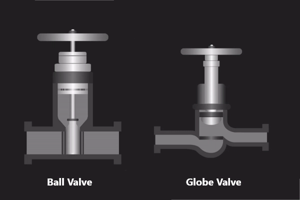
This complex path creates high turbulence and friction, leading to a much higher pressure drop. While a ball valve is ideal for on/off service with low energy loss, the globe design is purposely restrictive. This is what enables the precise regulation necessary for globe valves in flow control.
2. How to use the K-Factor in the Darcy-Weisbach Equation?
Experts and engineers use the Resistance Coefficient (K-factor) to identify the pressure drop across cast steel globe valves. It represents the number of velocity heads lost as fluid passes through the valve. Since the globe valve has a more restrictive design, it usually has a higher K-value (approximately 3.0 to 10.0) than ball valves (about 0.05).
Meanwhile, the Darcy-Weisbach equation was used in the 19th century to identify the pressure loss in straight pipes. The Darcy-Weisbach equation and the K-factor are used for fine-tuned throttling. The primary formula used in this guide is a variation of the Darcy-Weisbach equation:
ΔP = K * [ (ρ * v²) / 2 ]
Where:
- ΔP = Pressure drop (Pascals or psi)
- K = The dimensionless resistance coefficient of the valve
- ρ (rho) = Fluid density(kg/m³)
- v = Fluid velocity (m/s)
Take note that the K-factor is not a static number. For example, when a valve manufacturer declares a 7.0 K-factor if the valve is fully opened, that number can increase when the valve is closed. Calculating the pressure drop for several K-factors enables engineers to predict the system’s behavior at different phases of operation. This guarantees that industrial globe valves fit the pipe and perform efficiently under specific hydraulic stresses.
3. Key Variables Affecting Pressure Drop: Velocity and Viscosity
Besides the usual density and speed calculations, it’s also vital to know two of the most crucial variables in pressure drop – viscosity and velocity.
Velocity (v) is squared in the equation and is considered the most sensitive variable. If the flow velocity doubles, a quadrupled pressure drop is expected. Meanwhile, viscosity is key in identifying the flow regime, whether the fluid is flowing in smooth layers or chaotic swirls.
Look closely at the following steps. They help determine the pressure loss for a specific installation.
Step 1: Find out the Fluid Velocity (v)
Note the flow speed in meters per second. If it’s only the flow rate (Q), compute the velocity using v = Q/A. ‘A’ refers to the pipe’s cross-sectional area.
Step 2: Identify Fluid Density (ρ)
The medium density must be in kg/m³. Water at a standard temperature is about 1000 kg/m³. Densities might vary In industries that handle heavy chemicals.
Step 3: Locate the Valve K-Factor
The K-factor is usually provided in the technical data sheets from your valve manufacturer. Note that as the valve is throttled (closed), the effective K-factor increases. For a fully open industrial globe valve, 6.0 is a common average.
Step 4: Do the Equation
Input the variables into the Darcy-Weisbach formula.
4. Calculation Example
A facility manager opens a 4-inch industrial globe valve with a K-factor of 6.0 and pumps water with a density of 1000 kg/m³ at a velocity of 2 m/s.
- v²: 2×2=4
- Velocity head: (1000×4)/2=2000
- Final ΔP: 6.0×2000=12,000 Pascals (around 1.74 psi)
If the velocity increases to 4 m/s, expect the drop jumps to about 7 psi. Here lies the essence of maintaining liquid velocity within the recommended range of 5 to 10 feet per second. This prevents too much energy waste in globe valves for flow control.
Final Thoughts
Mastery in pressure drop calculation allows engineers and facility managers to optimize their systems. By understanding the relationship between the Darcy-Weisbach equation and the K-factor, experts can identify where energy is lost. This gives them the opportunity to take the initiative to reduce operational costs.
Most importantly, choosing the premium quality cast steel globe valves guarantees that globe valves for flow control provide the necessary regulation without compromise.


