
Matching pipe diameters is an important process in choosing the right hardware. But given the complexity of industrial piping, one must also have a clear understanding of the valve flow coefficient, also known as Cv. It serves as a definitive metric for determining the valve’s performance under specific flow and pressure conditions. Industries using globe valves for flow control treat the Cv value as the primary variable for balancing system performance with mechanical longevity.
Selecting a valve based solely on nominal pipe size often leads to systemic inefficiencies. Instead, a technical deep dive into flow coefficients allows operators to predict pressure drops and ensure that industrial globe valves operate within their intended performance window. This analysis explores the mechanical significance of Cv and its critical role in modern flow control optimization.
What is a Valve Flow Coefficient (Cv)?
The flow coefficient, or Cv, is a standardized mathematical value that represents a valve’s flow capacity. By definition, Cv is the volume of water at 60°F (in US gallons per minute) that will pass through a wide-open valve with a pressure drop of 1 psi. This coefficient was developed to provide a universal “language” for globe valve suppliers and engineers to compare the capacity of different valve designs regardless of their physical dimensions.
In globe valves for flow control, the internal geometry—specifically the “S-shaped” flow path—creates inherent resistance. The Cv accounts for such resistance by factoring the friction losses from the seat orifice, plug profile, and the valve body. Having a higher value means less resistance to flow, while a lower one indicates a more restrictive path.
How Oversized Valves Cause Control Instability?
Saying ‘bigger is better’ is a common misconception in piping design. However, oversized industrial globe valves are among the leading causes of control instability and premature mechanical failure. Too large valves for the required flow mean it must operate very close to the seat to maintain the desired setpoint.
This proximity creates several operational hazards, which include the following:
- Hunting and Oscillation: The control system will struggle to keep a stable position. The valve oscillates, which can eventually wear out the stems and the actuator. For example, in a real-world industrial plant facility, consistent cycling destabilizes pressure setpoints, which can lead to premature packing.
- Erosion and Cavitation: Wire-drawing and localized pressure drops can happen when a high-velocity fluid passes through narrow openings between the seat and the plug. This can trigger cavitation.
- Matching the valve Cv to the actual process requirements ensures that the hardware operates in its sweet spot. It’s generally between 20% and 80% of its travel, where control is the most stable and linear.
- How to Calculate Required Cv for Specific Flow Rates?Sensitivity: Even a small change in stem position can affect the flow, making precise regulation unattainable. For high-pressure systems, oversized valves might meet the required flow at about 5% of their total stroke.
Matching the valve Cv to the actual process requirements ensures that the hardware operates in its sweet spot. It’s generally between 20% and 80% of its travel, where control is the most stable and linear.
How to Calculate Required Cv for Specific Flow Rates?
To avoid the pitfalls of improper sizing, engineers must calculate the required Cv based on actual operating parameters rather than pipe size. The standard liquid flow formula for determining the required capacity is:

Where:
- Q = Flow rate in gallons per minute (GPM)
- SG = Specific gravity of the fluid (Water = 1.0)
- dP = Pressure drop across the valve in psi (P1 – P2)
The calculation above guarantees that globe valve suppliers can recommend the exact trim sizes that align with the hydraulic profile system. For gas or steam service, the calculation becomes more complex as it must account for compressibility and temperature. It is essential to calculate Cv for both the maximum expected flow and the minimum controlled flow.
This “turndown ratio” ensures that the globe valves for flow control remain effective across the entire operational range, preventing a precision control valve from functioning as a poorly-timed on-off valve.
Besides calculating the maximum expected flow, it’s also vital to compute Cv for the minimum controlled flow. It’s called the ‘turndown ratio’ and ensures the globe valve for flow control performs well across the operational range. For example, a valve’s maximum Cv is 100 with a minimum controlled flow of 2. This results in a turndown ratio of 50:1.
What is the relationship Between Cv and Pressure Drop?
The relationship between Cv and pressure drop is inverse and non-linear. In a flow control system, it’s expected that the valve will be the primary point of pressure drop. The ‘dissipitated energy’ is what allows for flow regulation. With a very high valve Cv, the pressure drop across the valve is negligible. This triggers the system piping to dictate the flow rate instead of the valve itself.
In high-performance industrial globe valves, maintaining a consistent pressure drop ratio is vital. If the pressure drop (dP) is very low (about 25%) relative to the total system pressure drop, the valve will lose its authority over the fluid. Meanwhile, an undersized valve with an insufficient Cv may result in a significant pressure drop.

If one moves the valve stem from 100% to 50% open, there’s no significant change in flow, making precision control impossible. This ‘distorts’ the valve, allowing it only to start regulating the fluid when it’s nearly closed.
To put it simply, an insufficient Cv with undersized valves can cause a huge pressure drop that can starve the downstream process. Furthermore, the pump will work much harder and waste more energy. For engineers, it’s crucial to maintain the balance to ensure a robust valve performance.
Final Thoughts
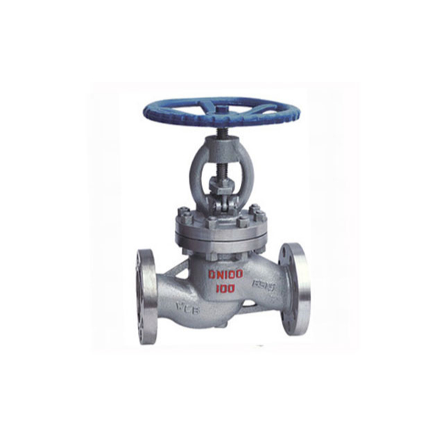
The flow coefficient is a key technical parameter for the right globe valves for flow control. Instead of merely focusing on pipe matching, make the Cv more significant to enable engineers to eliminate control instability, reduce mechanical wear, and optimize energy consumption.
Whether you’re sourcing from global globe valve suppliers or designing a new system, the goal must always be valve sizing. This keeps the authority over the fluid without introducing adverse effects. Properly sized industrial globe valves are the foundation of an efficient and reliable flow control system.


